In SketchUp, a component (or as a matter of fact, a group too) can be "glued" to a face and also cut an opening on it. This feature allows modellers to quickly place windows, doors etc. on the faces of a building and immediately make a virtual opening on it without having to physically "cut" that hole on the face. These components can be moved on this face without their cutting feature lost.
Unfortunately, a component can only have one gluing (cutting) plane so a simple component cannot cut only one face which means we need to apply workarounds for thick walls (described in another tutorial).
Creating the Component
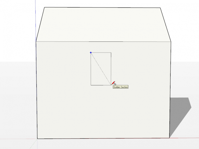
The easiest way to start with such a component is to draw it on an already existing face (e.g. the wall of your building). Here is a schematic "house" I quickly modelled - and see how you start with a simple rectangle.
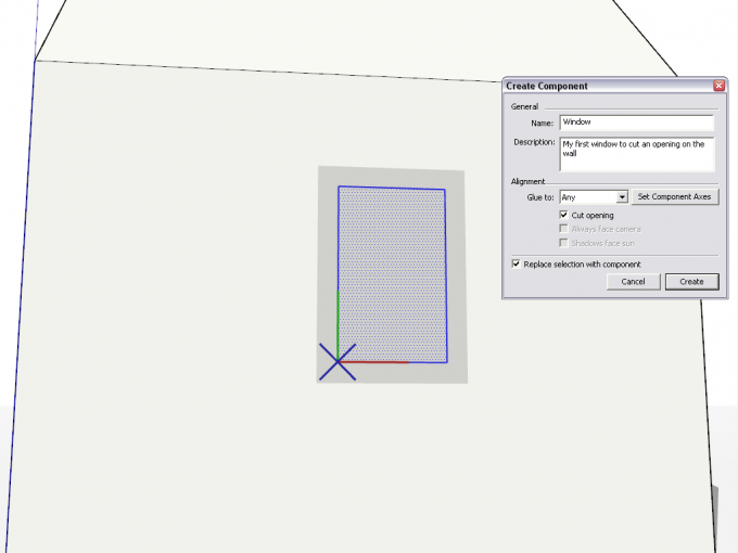
Next, before you add any details, double click on your rectangle (to select its face and bounding edges) then right click and "Make component".
There are a couple of things to be noted here:
- Although the geometry we selected previously "touches" other geometry (the face surrounding it), the "Replace selected" box at the bottom left is checked (it is usually not in such cases).
- The component to be created is already set to glue to faces (by default, to "any") and set to cut opening.
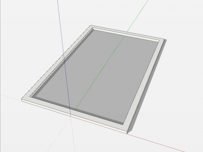
- If you look at the rectangle, a grey plane is displayed. This is the "gluing plane" and in this kind of components, it always have to be on the face we want it to glue to. The blue axis is "X'ed out" and the gluing plane is on the red/green plane of the component. This is very important.
Also, though any component can be set to glue, it is important to note that in order to cause the component to in fact cut a hole, there must be a closed loop of coplanar edges on the gluing plane inside the component. They must be "loose geometry" at the topmost level of the component (i.e. not nested in subcomponents or groups). This is a very often overlooked condition which makes new users stumped when the incidentally delete the whole or part of this closed loop or move geometry inside the component relative to its axes.
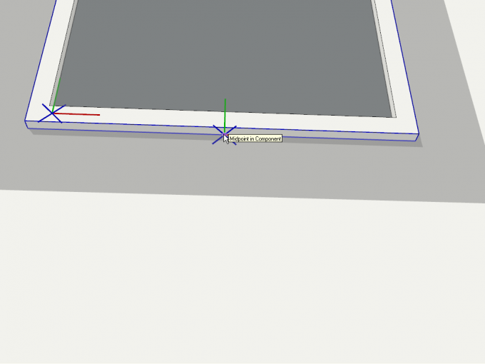
At this point, we can also set (move) the component axes (there is that button in the Create component window). Of course, it must remain on the same plane where the rectangle is (note the above) but it might be more convenient to set it to the midpoint of the bottom edge. We can (and in this tutorial, will) do this later though. The component origin is important because by default, that is the insertion point at which we "grab" the component when inserting it from the Component browser.
It is important to remember that components can only cut a hole on a bare face. Not on a face inside a group of other component (unless of course you move the window component inside to place it on a face of raw geometry).
All right, save your component at this early stage (a simple rectangle) and let's start tweaking it.
Modifying the Component
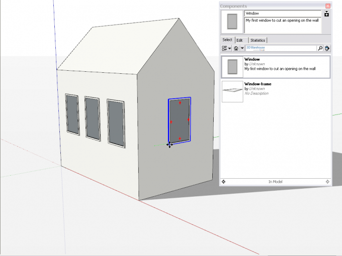
Now if you double click on the component, you can modify it; add detail, texture it etc. I used the offset tool to make an outer offset then the PushPull tool to give that offset a thickness and created a window frame this way. I also made this window frame a component inside the main component (this is called a "nested component") then painted the original rectangle with a transparent grey colour from the Translucent material library.
Our component is "ready" to be inserted from the Component browser and no matter what face I am placing it on, it adjusts itself to align with its gluing plane to that face and cuts the opening
In the component browser however, you can see the window frame separately as a component. If you have many sublevel components like this (which you'd never use independently) in your model, you can make them external components to collapse child level components inside.
Modifying the Component Axes
As was mentioned before, often it is handy to have the component origin at a certain point in the component so that when you grab it from the Component browser, it is already inserted by this point. If we missed to do this when we were creating the component, we can always right click on any inserted instance of the component in the model and select "Change axes" from the context menu.
Again: make sure that you do not change the gluing plane and only simply move the origin to a more convenient spot. Click to establish the new axis and it will change it to every instance inside the model.
Editing the Component as an External File
If you right click on the component either inside the model or in the Component browser and select "Save as", you can save it as a separate SketchUp file (with the usual *.skp extension). You can open it, modify it and reload it as you wish (and as it's described in that other tutorial above). A component that has gluing property, as you could see under the "Creating the Component" heading, has its blue axis perpendicular to the gluing plane (which is always the red/green axis). This results in a component with a gluing property set come in lying on its back when opened externally.
Notice that it's not a "component" now but a set of raw geometry and other components/groups you may have created as nested child components previously. You can do whatever with your component now except:
- Move the component away from its component origin (especially along the blue axis). Note that the model origin here will always be the component origin when reloaded and you can easily mess up its gluing/cutting properties
- Delete or discontinue somehow the closed loop of coplanar edges that make sure that your window actually cuts a hole in the face it is placed on (and not only glues to it).
After modifying anything else you wish, you can save your component and reload it in your "master model".


